Strike and dip measurements can be entered into the RockWorks datasheet for the purposes of creating strike and dip maps, stereonet diagrams, and computing planar intersections, structure grids, and more. There are a variety of ways you can structure these files, depending on your desired output.
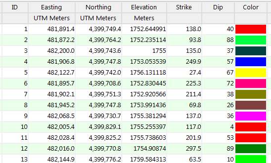
This example lists site-specific strike and dip measurements, with strike shown in azimuth bearings. These data could be displayed as a strike and dip map or stereonet diagram, analyzed for planar intersections, interpolated into a structural surface, etc.
Column Summary
- ID: Optional. Lists the sample number or name for each site.
- X (Easting), Y (Northing) Coordinates: Required for strike and dip maps. Optional for stereonet plots. (See Example 3, below.)
These can be entered in meters or feet, decimal longitudes, etc. See Defining your Datasheet Coordinates for more information.- Z (Elevation) Coordinates: Required for grid models created from structure data.
These can be in meters or feet, but you need to be sure that you've defined the units in the column headings. See Defining your Datasheet Coordinates for details.- Direction: Required. Lists the azimuth bearing of the feature. It can represent strike or dip bearing, in 0 - 360 degree format. Dip direction is assumed to be clockwise from strike bearing (right hand rule); most programs permit you to define whether it's a strike or dip bearing.
You may also enter bearing in quadrant notation, see Example 2, below.)- Dip angle: Lists the dip angle, with 0 = horizontal and 90 = straight down.
- Rake angle (not shown above): If you are entering rake angles for lineations measured on planar surfaces, then you will need to enter this third measurement after the strike and dip (above). During creation of the stereonet diagram (stereonets only), the program will convert the rake to the true linear feature. If you are entering rake data, the program assumes that the strike bearing and dip angle (above) are for the plane upon which the rake was measured. The rake angle must be measured down from horizontal, clockwise of the strike direction. If your planar data is in the dip direction / dip angle format, you must be sure that the angle is measured from the strike line and not from the dip direction.
- Color: Optional. Used for strike and dip maps, though not required. (A fixed color can be selected if necessary.)
This example lists site-specific strike and dip measurements, with strike shown in quadrant format.

Column Summary
- See Example 1, above.
- ! Note that the dip angle must NOT include any directional notation.
This example lists strike and dip measurements with no X,Y location coordinates. This setup could be used to create stereonet diagrams, with specific symbols for the samples.
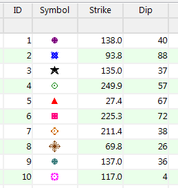
Column Summary
- ID: Optional. Lists the sample number or name for each site.
- Symbol: Optional. The Stereonet program can plot the lineations or the poles to planes using either variable symbols (read from the datasheet as above) or fixed symbols (declared in the program dialog box).
- Direction: Required. Lists the azimuth bearing of the feature. It can represent strike or dip bearing, in 0 - 360 degree format. Dip direction is assumed to be clockwise from strike bearing (right hand rule); most programs permit you to define whether it's a strike or dip bearing.
- Dip angle: Lists the dip angle, with 0 = horizontal and 90 = straight down.
![]()