The Model Dimensions options are used to establish the boundary coordinates and the number of nodes to be created in the solid model.
The more nodes you specify, the denser the model. Remember that a 10-node x 10-node x 10-node model (very low resolution) will contain 1,000 nodes; a 50-node x 50-node x 50-node model will contain 125,000 nodes; and a 100 x 100 x 100 model will contain 1 million nodes. The more computations the program needs to do, the longer the time required to create the model. Denser is not always better. You might create less-dense models on trial runs.
Menu Options
- Hardwire Output Dimensions: Recommended. Choose this dimensioning option if the solid model dimensions are to be taken from the current Output Dimensions settings. This is usually a good idea, particularly in projects where multiple models are going to be created and may need to undergo comparison, mathematical, and filtering operations, because all models must be dimensioned the same. Expand this heading if you wish to view or reset these settings.
-
- Adjust Output Dimensions: Click on this item to view and/or reset the output dimensions. These are the same settings you can access in the Output Dimensions pane at the top of the RockWorks program window. See Output Dimensions for more information.
- Variable (Data-Specific) Dimensions: Choose this dimensioning option if the solid model dimensions are to be established based on the current data being modeled. This could be an option for modeling a subset of the entire project or for testing the effect of different node densities without having to reset the entire project's dimensions. Expand this heading to select the variable options for Solid Dimensions.
-
- Horizontal: Type here the number of nodes to be created from west to east and from north to south. The boundary defaults will correspond to the outermost control point locations.
-
- The number of nodes you declare will be modified if the map area is not square. In trying to keep node spacing as close to equal as possible along both axes, the program will reduce the number of nodes created along the area's short axis. If you request dimension confirmation, below, you will have the opportunity to view and confirm the program-recommended node spacing prior to model generation.
- Vertical: Type here the number of nodes to be created vertically in the model. This axis can be set to a different density that the X and Y (Horizontal) axes, above. The boundary defaults will correspond to the lowest and highest control point elevations. If you request dimension confirmation, below, you will have the opportunity to view and confirm the program-recommended node spacing prior to model generation.
- Insert a check in the Confirm Dimensions box to request display of program-computed model dimensions and node spacing prior to modeling. At that time you can view and override the defaults.
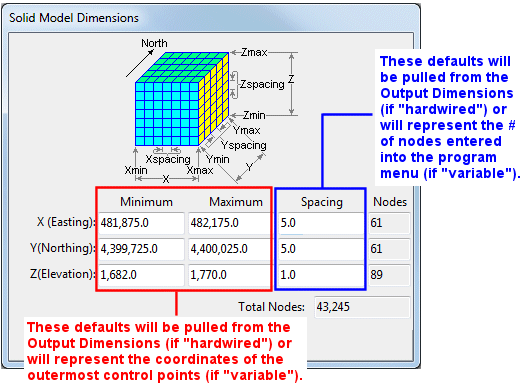
- If this window is displayed, you can adjust any of the coordinate boundary or spacing settings.

RockWare home page