This is a solid modeling method that is used for creating lithology solid models in the Borehole Manager. This technique is also available for downhole quantitative data (e.g. I-data, T-Data, P-data) to provide a means for creating models of data that are horizontally contiguous but numerically discrete. This was previously included in the "horizontal lithoblending" algorithm.
The Lateral Blending method looks outward horizontally from each data point, in search circles of ever-increasing diameter. It first assigns the voxels immediately surrounding each borehole the closest lithology or real number value. It then moves out by a voxel, and assigns the next "circle" of voxels the closest lithology value.
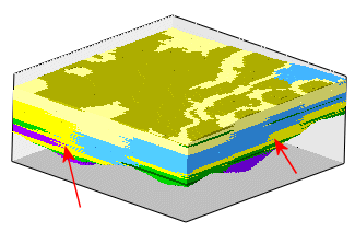
Unlike the Lateral Extrusion method, it continues in this manner until it reaches a point about a third of the way to neighboring data points. Then, in the center areas, it applies a randomizing algorithm to minimize the abrupt changes between material types. This produces a more blended model, more like a geologist might draw by hand. You can refer to the 3D diagram and cross section below. ! Note: Because it's a randomized process, successive models created from the same data will look slightly different.

For lithology data, the numeric values assigned to each material in the Lithology Types Table are extruded outward from the boreholes into the 3D space of the model.
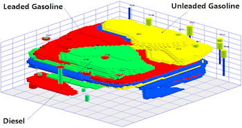
For quantitative data, the lateral extrusion algorithm will conceptually "bleed" measured values outward from the boreholes outwards, coalescing with the adjacent boreholes, without creating gradations. The example below illustrates LIF (Laser Induced Fluorescence) measurements for hydrocarbons in which the data consists of discrete values (e.g. 0.0 = uncontaminated, 1.0 leaded gasoline, 2.0 = unleaded gasoline, and 3.0 = diesel).
Two methods of the lateral "bleeding" are offered - one which extrudes simulataneously out from the holes, with "randomization", and one which simply grabs the closest neighboring point.
Menu Options
Interpolate Outliers: Insert a check in this option to assign all model voxels a G value. If you remove the check-mark from this setting, any "outlying" nodes, positioned either in the center zones between points or in outer zones beyond a cutoff distance or, will be assigned the Undefined value (e.g. null), thus making them invisible in the output model. The cutoff distance is defined as the distance between a well and its closest neighboring well.

![]() Back to Solid Modeling Method Summary
Back to Solid Modeling Method Summary
![]()