RockWorks | Utilities | Imagery |
Rectify (Rotate/Scale/Clip Image -> New Map)
This program is used to calibrate, rotate and clip airphotos and satellite images to project dimensions. Optional generation of an accompanying World file is available. Supported bitmap formats include: BMP, JPG, EMF, WMF, PCX, PNG, TGA, and TIFF.
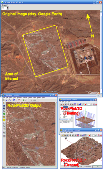
The basic idea behind this program is to take an image, calibrate it to user-defined coordinates, rotate it such that the edges are aligned to a north/south, east/west orientation, and then to clip (extract) the portion of the image that corresponds to a rectangular area of interest. Subsequent uses for the output image include backgrounds for 2D maps and draped/floating images for 3D diagrams.
Menu Options
Step-by-Step Summary
Menu Options
- Input File: Click to the right to browse for the image to be rectified. The supported file formats are listed above.
- Output (Rotated/Clipped) Image: Click to the right to type in a name for the new image to be saved by RockWorks. The supported formats are shown above. We recommend you save images to be used with the current project data, to the current project folder.
- Create "World File": Check this box if you would like to create a "World File" that can be used in GIS (Geographic Information Systems) programs in order to correctly register (locate) an image relative to a mapping coordinate system.
- Naming Convention: Expand this heading to define how the World File name extension will be assigned. (The file name itself - the part before the "." - will be the same as the output image name.)
- Append "W" To Output Extension: Choose this option if the file name extension of the World File should have the output file name extension plus the character "w". Example: If the rotated/clipped output image is named "Project 27.jpg", the World File will be named "Project 27.jpgw".
- 3-Character Format: Choose this option if the file name extension of the World File should have 3-characters:
- The first character of the extension will equal the first character of the output file extension.
- The second character of the extension will be equal to the last character of the output file extension.
- The third character of the extension will be set to "W".
- Example: If the rotated/clipped output image is named "Project 27.jpg", the World File will be named "Project 27.jgw".
- Calibration Point Coordinates: Use these settings to define the real world coordinates for three known points on the image. They can be in any orientation, but remember the order in which you list them - you'll need to click on the points, interactively, in the same order in the next step of the process.
- Point 1: Click on the X and Y prompts to type in the X and Y coordinates for the first known point on the image.
- Point 2: Click on the X and Y prompts to type in the X and Y coordinates for the second known point on the image.
- Point 3: Click on the X and Y prompts to type in the X and Y coordinates for the third known point on the image.
- Clip Image: Insert a check here if you want to crop the image, and establish the crop dimensions below.
- Based on Project Dimensions: Choose this option to have the program crop the image using the current output dimensions.
- Based on Custom Dimensions: Choose this option to type in specific clipping coordinates. Expand this heading to enter these coordinates.
- Western Border (X-Min): Click here to type in the coordinate that is to become the left (western) edge of the image.
- Southern Border (Y-Min): Click here to type in the coordinate that is to become the lower (southern) edge of the image.
- Eastern Border (X-Max): Click here to define the coordinate that is to become the right (eastern) edge of the image.
- Northern Border (Y-Max): Click here to define the coordinate that is to become the upper (northern) edge of the image.
- List Image Dimensions within Windows Notepad: Insert a check here if you want the program to list the outer image coordinates in a text file, which you can save in your project folder. These will represent the clip edges, if you have clipping activated (above) or simply the rectified image if no clipping was requested.
! This can be very handy if you will be displaying the image in RockPlot2D or RockPlot3D in a later session - you'll need to know the image boundary coordinates.
- Export New (Rectified) Image to ...
- RockPlot2D: Insert a check here to have the image displayed in RockPlot2D using the image dimensions you've defined. You can request both 2D and 3D display (below).
- RockPlot3D:
- Drape Image over Grid Model: Insert a check in this box to drape the image over a grid (surface) model that exists in your project. Expand this heading to establish the drape settings.
! Important: This tool will stretch the image to fill the grid model boundaries. It assumes that the image edges match the grid model edges.
- Grid Model: Click on this to select the name of the surface model (.RwGrd file) that contains the elevations over which the image is to be draped. For example, if you have been working in the Borehole Manager, you might want to look in the Project Manager for an .RwGrd file with the name of your upper-most formation.
- Layer Name: Type in a name for this layer; it will simply be used to label the bitmap in RockPlot3D. For example, if the image represents a satellite image, you might name this layer "Satellite Image."
- Set Transparent Color: Insert a check in this box if you want to specify a specific color in the raster image to be displayed transparent. If activated, expand this heading to click on the color box to choose the image color that is to be set to transparent. For example if the image has a white background and you would like that part to be see-through, you would select white.
- ! Note that this transparent-color selection is fairly precise. In high color images there can be considerable variation of white, for example, which can make it tricky to set broad transparency. For this reason, as well as for reasons of speed, it’s best to keep the bitmap colors to as few as possible.
- Vertical Offset: Use this setting to offset the image above or below the grid surface, expressed in your elevation units. This can make the image and surface more easily visible in RockPlot3D.
- Float Image at Specified Elevation: Click in this box to float the image as a flat surface. Expand this heading to establish the float settings:
- Elevation: Click here to type in the elevation at which the bitmap is to be floated.
- Layer Name: Type in a name for this layer; it will simply be used to label the floating bitmap in RockPlot3D. For example, if the image represents a satellite image, you might name this layer "Satellite Image."
- Set Transparent Color: Insert a check in this box if you want to specify a specific color in the bitmap image to be displayed transparent. See the notes listed above, under Drape.
- Reference Cage: Insert a check here to include reference labels or lines in the output 3D image. More
Step-by-Step Summary
- The Rectify-Image program reads an existing raster image; be sure you have that handy.
- Access the RockWorks Utilities program tab.
- Select the Imagery | Rectify (Rotate/Scale/Clip Image -> New Map) menu option.
- Enter the menu settings, described above.
- Click the Process button to proceed.
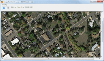
The program will display the selected image on the screen. At the top of this display window, you'll see a prompt to "Click on Point #1 (of 3)".
- Using your mouse, click on the point on the image that represents your calibration Point #1. If necessary, you can adjust the view size using the "Size (%)" prompt in the upper-left corner. Increasing this number (by typing in a value, or by clicking the up-arrow) will offer a zoomed-in view of the image. Decreasing this number will offer a zoomed-out view of the image.
When you've clicked the first point, you'll see it posted on the image.
- Click the point on the image that represents your calibration Point #2. It also will be posted on the image.
- Click the point on the image that represents your calibration Point #3.
- The program will rotate the image as necessary, clip it as requested, and display it as requested:
- It will also display a Notepad window with the image boundary coordinates if requested.
 Back to Imagery Menu Summary

RockWare home page